- 您現(xiàn)在的位置:買賣IC網(wǎng) > PDF目錄384407 > HI-15530PSMF (HOLT INTEGRATED CIRCUITS INC) 5V / 3.3V Manchester Encoder / Decoder PDF資料下載
參數(shù)資料
| 型號(hào): | HI-15530PSMF |
| 廠商: | HOLT INTEGRATED CIRCUITS INC |
| 元件分類: | 網(wǎng)絡(luò)接口 |
| 英文描述: | 5V / 3.3V Manchester Encoder / Decoder |
| 中文描述: | DATACOM, MANCHESTER ENCODER/DECODER, PDSO24 |
| 封裝: | ROHS COMPLIANT, PLASTIC, SSOP-24 |
| 文件頁數(shù): | 4/12頁 |
| 文件大小: | 279K |
| 代理商: | HI-15530PSMF |
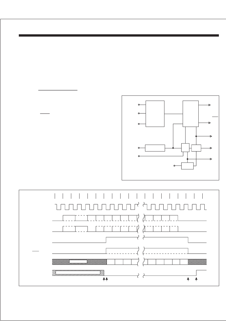
The Decoder requires a single clock with a frequency of 12
times the desired data rate applied at the DECODER
CLOCK input. The Manchester II coded data can be
presented to the Decoder in one of two ways. The
BIPOLAR ONE and BIPOLAR ZERO inputs will accept
datafromacomparatorsensedtransformercoupledbusas
specified in MIL-STD-1553. The UNIPOLAR DATA input
can only accept non-inverted Manchester II coded data
(e.g. from
Decoder is free running and continuously monitors its data
input lines for a valid sync character and two valid
Manchester data bits to start an output cycle. When a valid
sync is recognized (1), the type of sync is indicated on
COMMAND/
SYNC output. If the sync character was
a command sync, this output will go high (2) and remain
high for sixteen DECODER SHIFT CLOCK periods (3),
otherwise it will remain low. The TAKE DATA output will go
high and remain high (2) - (3) while the Decoder is
transmitting the decoded data through SERIALDATAOUT.
The decoded data available at SERIAL DATAOUT is in an
NRZ format.The DECODER SHIFTCLOCK is provided so
thatthedecodedbitscanbeshiftedintoanexternalregister
on every low-to-high transition of this clock (2) - (3).After all
sixteen decoded bits have been transmitted (3) the data is
checked for odd parity. A high on VALID WORD output (4)
indicates a successful reception of a word without any
Manchester or parity errors. At this time the Decoder is
of an Encoder). The
BIPOLAR ZERO OUT
DATA
HI-15530
HOLT INTEGRATED CIRCUITS
4
DECODER OPERATION
0
1
2
3
4
5
6
7
16
17
18
19
15
14
13
12
11
2
1
0
P
2
1
0
P
15
14
13
12
11
SYNC
SYNC
SYNC
15
14
13
12
3
2
1
0
SYNC
(1)(2)
(3)
(4)
May be high from previous reception
VALID WORD
DECODER
SHIFT CLK
TIMING
TAKE DATA
SERIAL
DATA OUT
BIPOLAR
ONE IN
BIPLOAR
ZERO IN
FIGURE 4. DECODER OPERATION
8
COMMAND /
DATA
SYNC
10
10
4
UNDEFINED
TAKE DATA
UNIPOLAR
DATA IN
BIPOLAR
ONE IN
BIPOLAR
ZERO IN
MASTER
RESET
DECODER
CLK
DECODER
RESET
COMMAND/
SYNC
DATA
SERIAL DATA
OUT
VALID
WORD
DECODER
SHIFT CLK
TRANSITION
FINDER
CHARACTER
IDENTIFIER
SYNCHRONIZER
BIT
COUNTER
BIT
RATE
CLK
PARITY
CHECK
FIGURE 3. DECODER
looking for a new sync character to start another output
sequence. VALID WORD will go low approximately 20
DECODER SHIFT CLOCK periods after it goes high if not
reset low sooner by a valid sync and two valid Manchester
bits as shown (1). At any time in the above sequence, a
high input on DECODER RESET during a low-to-high
transition of DECODER SHIFT CLOCK will abort
transmission and initialize the Decoder to start looking for a
newsynccharacter.
相關(guān)PDF資料 |
PDF描述 |
|---|---|
| HI-15530PSTF | 5V / 3.3V Manchester Encoder / Decoder |
| HI-1566PSIF | 5V Monolithic Dual Transceivers |
| HI-1566CDT | 5V Monolithic Dual Transceivers |
| HI-1566PCI | 5V Monolithic Dual Transceivers |
| HI-1566PCIF | 5V Monolithic Dual Transceivers |
相關(guān)代理商/技術(shù)參數(shù) |
參數(shù)描述 |
|---|---|
| HI-15530PST | 制造商:HOLTIC 制造商全稱:Holt Integrated Circuits 功能描述:5V / 3.3V Manchester Encoder / Decoder |
| HI-15530PSTF | 制造商:HOLTIC 制造商全稱:Holt Integrated Circuits 功能描述:5V / 3.3V Manchester Encoder / Decoder |
| HI1-5618A-8 | 制造商:未知廠家 制造商全稱:未知廠家 功能描述:8-Bit Digital-to-Analog Converter |
| HI1-562A-2 | 制造商:未知廠家 制造商全稱:未知廠家 功能描述:12-Bit Digital-to-Analog Converter |
| HI1-562A-4 | 制造商:未知廠家 制造商全稱:未知廠家 功能描述:12-Bit Digital-to-Analog Converter |
發(fā)布緊急采購,3分鐘左右您將得到回復(fù)。