- 您現(xiàn)在的位置:買賣IC網(wǎng) > PDF目錄384407 > HI-15530PSM (HOLT INTEGRATED CIRCUITS INC) 5V / 3.3V Manchester Encoder / Decoder PDF資料下載
參數(shù)資料
| 型號: | HI-15530PSM |
| 廠商: | HOLT INTEGRATED CIRCUITS INC |
| 元件分類: | 網(wǎng)絡(luò)接口 |
| 英文描述: | 5V / 3.3V Manchester Encoder / Decoder |
| 中文描述: | DATACOM, MANCHESTER ENCODER/DECODER, PDSO24 |
| 封裝: | PLASTIC, SSOP-24 |
| 文件頁數(shù): | 3/12頁 |
| 文件大小: | 279K |
| 代理商: | HI-15530PSM |
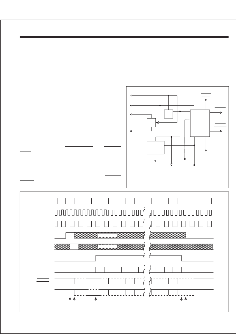
ENCODER OPERATION
HI-15530
HOLT INTEGRATED CIRCUITS
3
The Encoder requires a single clock with a frequency of
twice the desired data rate applied at the SEND CLOCK
input.An auxiliary divide-by-six counter is provided on chip
which can be utilized to produce the SEND CLOCK by
dividingtheENCODERCLOCK.
The Encoder's cycle begins when ENCODER ENABLE is
high during a falling edge of ENCODER SHIFTCLOCK (1).
This cycle lasts for one word length or twenty ENCODER
SHIFTCLOCK periods.At the next low-to-high transition of
the ENCODER SHIFT CLOCK, a high at SYNC SELECT
input actuates a command sync or a low will produce a
data sync for that word (2). When the Encoder is ready to
accept data, the SEND DATA output will go high and
remain high for sixteen ENCODER SHIFT CLOCK periods
(3). During these sixteen periods the data should be
clocked into the SERIAL DATA IN input with every low-to-
high transition of the ENCODER SHIFT CLOCK (3) - (4).
After the sync and the Manchester II coded data are
transmitted through the
outputs,theEncoderaddsonanadditionalbitwhich
is the parity for that word (5). If ENCODER ENABLE is held
high continuously, consecutive words will be encoded
without an interframe gap. ENCODER ENABLE must go
low by time (5) as shown to prevent a consecutive word
from being encoded. At any time a low on the
input will force both bipolar outputs to a high state
butwillnotaffecttheEncoderinanyotherway.
and
BIPOLAR ONE
BIPOLAR
ZERO
OUTPUT
INHIBIT
0
1
2
3
4
5
6
7
15
16
17
18
19
15
14
13
12
11
3
2
1
0
P
3
2
1
0
P
15
14
13
12
11
SYNC
SYNC
SYNC
15
14
13
12
11
3
2
1
0
10
SYNC
VALID
(1) (2)
(3)
(4) (5)
DON’T CARE
DON’T CARE
SYNC SELECT
ENCODER
ENABLE
ENCODER
SHIFT CLK
SEND CLK
TIMING
SEND DATA
SERIAL
DATA IN
BIPOLAR
ONE OUT
BIPLOAR
ZERO OUT
FIGURE 2. ENCODER OPERATION
Bit
Counter
Character
Former
MASTER RESET
SEND CLK IN
6 OUT
ENCODER CLK
SEND
DATA
ENCODER
SHIFT
CLK
IN
ENABLE
SYNC
SELECT
OUTPUT
INHIBIT
BIPOLAR
ONE OUT
BIPOLAR
ZERO OUT
FIGURE 1. ENCODER
SERIAL
DATA
ENCODER
To abort the Encoder transmission a positive pulse must be
applied at MASTER RESET. Anytime after or during this
pulse, a low to high transition on SEND CLOCK clears the
internal counters and initializes the Encoder for a new
word.
相關(guān)PDF資料 |
PDF描述 |
|---|---|
| HI-15530PSMF | 5V / 3.3V Manchester Encoder / Decoder |
| HI-15530PSTF | 5V / 3.3V Manchester Encoder / Decoder |
| HI-1566PSIF | 5V Monolithic Dual Transceivers |
| HI-1566CDT | 5V Monolithic Dual Transceivers |
| HI-1566PCI | 5V Monolithic Dual Transceivers |
相關(guān)代理商/技術(shù)參數(shù) |
參數(shù)描述 |
|---|---|
| HI-15530PSMF | 制造商:HOLTIC 制造商全稱:Holt Integrated Circuits 功能描述:5V / 3.3V Manchester Encoder / Decoder |
| HI-15530PST | 制造商:HOLTIC 制造商全稱:Holt Integrated Circuits 功能描述:5V / 3.3V Manchester Encoder / Decoder |
| HI-15530PSTF | 制造商:HOLTIC 制造商全稱:Holt Integrated Circuits 功能描述:5V / 3.3V Manchester Encoder / Decoder |
| HI1-5618A-8 | 制造商:未知廠家 制造商全稱:未知廠家 功能描述:8-Bit Digital-to-Analog Converter |
| HI1-562A-2 | 制造商:未知廠家 制造商全稱:未知廠家 功能描述:12-Bit Digital-to-Analog Converter |
發(fā)布緊急采購,3分鐘左右您將得到回復。