- 您現(xiàn)在的位置:買賣IC網(wǎng) > PDF目錄384407 > HI-15530PSIF (HOLT INTEGRATED CIRCUITS INC) 5V / 3.3V Manchester Encoder / Decoder PDF資料下載
參數(shù)資料
| 型號: | HI-15530PSIF |
| 廠商: | HOLT INTEGRATED CIRCUITS INC |
| 元件分類: | 網(wǎng)絡(luò)接口 |
| 英文描述: | 5V / 3.3V Manchester Encoder / Decoder |
| 中文描述: | DATACOM, MANCHESTER ENCODER/DECODER, PDSO24 |
| 封裝: | ROHS COMPLIANT, PLASTIC, SSOP-24 |
| 文件頁數(shù): | 2/12頁 |
| 文件大小: | 279K |
| 代理商: | HI-15530PSIF |
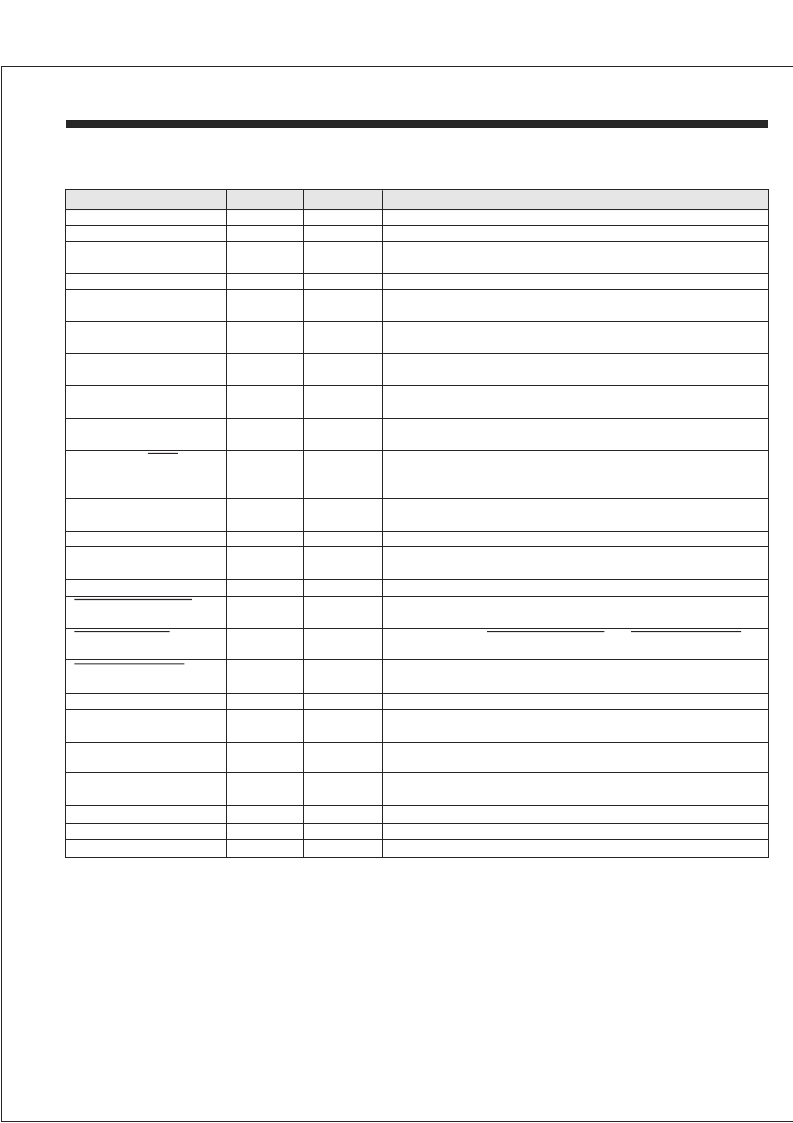
SIGNAL
VALID WORD
ENCODER SHIFT CLOCK
TAKE DATA
SECTION
DECODER
ENCODER
DECODER
FUNCTION
OUTPUT
OUTPUT
OUTPUT
DESCRIPTION
A high output signals the receipt of a valid word
Shifts data into the encoder on a low to high transition
Output is high during receipt of data after identification of a Sync
Pulse and two valid Manchester data bits.
Received Data output in NRZ format
12x the data rate. Clock for the transition finder and synchronizer,
which generates the internal clock for the remainder of the decoder
A high input indicates the 1553 bus is in its negative state.
This pin must be held high when the Unipolar input is used
A high input indicates the 1553 bus is in the positive state.
This pin must be held low when the Unipolar input is used
Input for unipolar data to the transition finder. Must be held low when
Not in use
Provides the DECODER CLOCK divided by 12, synchronized by the
recovered serial data
A high on this pin occurs during the output of decoded data which
was preceded by a Command (or Status) synchronizing character. A
low output indicates a Data synchronizing character
A high applied to this pin during a DECODER SHIFT CLOCK rising
edge resets the bit counter
0V supply
A high on this pin clears the 2:1 counters in both Encoder and
Decoder and resets the divide-by-6 circuit
Provides ENCODER CLOCK divided by 6
SERIAL DATA OUT
DECODER CLOCK
DECODER
DECODER
OUTPUT
INPUT
BIPOLAR ZERO IN
DECODER
INPUT
BIPOLAR ONE IN
DECODER
INPUT
UNIPOLAR DATA IN
DECODER
INPUT
DECODER SHIFT CLOCK
DECODER
OUTPUT
COMMAND /
SYNC
DECODER
OUTPUT
DECODER RESET
DECODER
INPUT
GND
MASTER RESET
BOTH
BOTH
POWER
INPUT
6 OUT
ENCODER
OUTPUT
ENCODER
OUTPUT
An active low output intended to drive the zero or negative sense of
a MIL-STD-1553 Line Driver
A low inhibits the
forcing them to inactive high states
An active low output intended to drive the one or positive sense on a
MIL-STD-1553 Line Driver
Accepts serial data at the rate of the ENCODER SHIFT CLOCK
A high on this pin initiates the encode cycle. (Subject to the
preceeding cycle being complete)
Actuates a Command Sync for an input high and a Data Sync for a
low
An active high output which enables the external source of serial
Data
Clock input at 2 times the Data rate, usually driven by
ENCODER
INPUT
and
by
ENCODER
OUTPUT
SERIAL DATA IN
ENCODER ENABLE
ENCODER
ENCODER
INPUT
INPUT
SYNC SELECT
ENCODER
INPUT
SEND DATA
ENCODER
OUTPUT
SEND CLOCK IN
ENCODER
INPUT
6 OUT
ENCODER CLOCK
VDD
ENCODER
BOTH
INPUT
POWER
Input to the divide by 6 circuit. Normal frequency is Data rate x12
3.0 V to 5.5 V power supply pin
DATA
BIPOLAR ZERO OUT
OUTPUT INHIBIT
BIPOLAR ZERO OUT
BIPOLAR ONE OUT
BIPOLAR ONE OUT
PIN DESCRIPTIONS
HOLT INTEGRATED CIRCUITS
2
HI-15530
相關(guān)PDF資料 |
PDF描述 |
|---|---|
| HI-15530PSM | 5V / 3.3V Manchester Encoder / Decoder |
| HI-15530PSMF | 5V / 3.3V Manchester Encoder / Decoder |
| HI-15530PSTF | 5V / 3.3V Manchester Encoder / Decoder |
| HI-1566PSIF | 5V Monolithic Dual Transceivers |
| HI-1566CDT | 5V Monolithic Dual Transceivers |
相關(guān)代理商/技術(shù)參數(shù) |
參數(shù)描述 |
|---|---|
| HI-15530PSM | 制造商:HOLTIC 制造商全稱:Holt Integrated Circuits 功能描述:5V / 3.3V Manchester Encoder / Decoder |
| HI-15530PSMF | 制造商:HOLTIC 制造商全稱:Holt Integrated Circuits 功能描述:5V / 3.3V Manchester Encoder / Decoder |
| HI-15530PST | 制造商:HOLTIC 制造商全稱:Holt Integrated Circuits 功能描述:5V / 3.3V Manchester Encoder / Decoder |
| HI-15530PSTF | 制造商:HOLTIC 制造商全稱:Holt Integrated Circuits 功能描述:5V / 3.3V Manchester Encoder / Decoder |
| HI1-5618A-8 | 制造商:未知廠家 制造商全稱:未知廠家 功能描述:8-Bit Digital-to-Analog Converter |
發(fā)布緊急采購,3分鐘左右您將得到回復。