- 您現(xiàn)在的位置:買賣IC網(wǎng) > PDF目錄384392 > HC1-5504B-5 (HARRIS SEMICONDUCTOR) EIA/ITU PABX SLIC with 40mA Loop Feed PDF資料下載
參數(shù)資料
| 型號(hào): | HC1-5504B-5 |
| 廠商: | HARRIS SEMICONDUCTOR |
| 元件分類: | 模擬傳輸電路 |
| 英文描述: | EIA/ITU PABX SLIC with 40mA Loop Feed |
| 中文描述: | TELECOM-SLIC, CDIP24 |
| 文件頁(yè)數(shù): | 2/9頁(yè) |
| 文件大?。?/td> | 265K |
| 代理商: | HC1-5504B-5 |
8-20
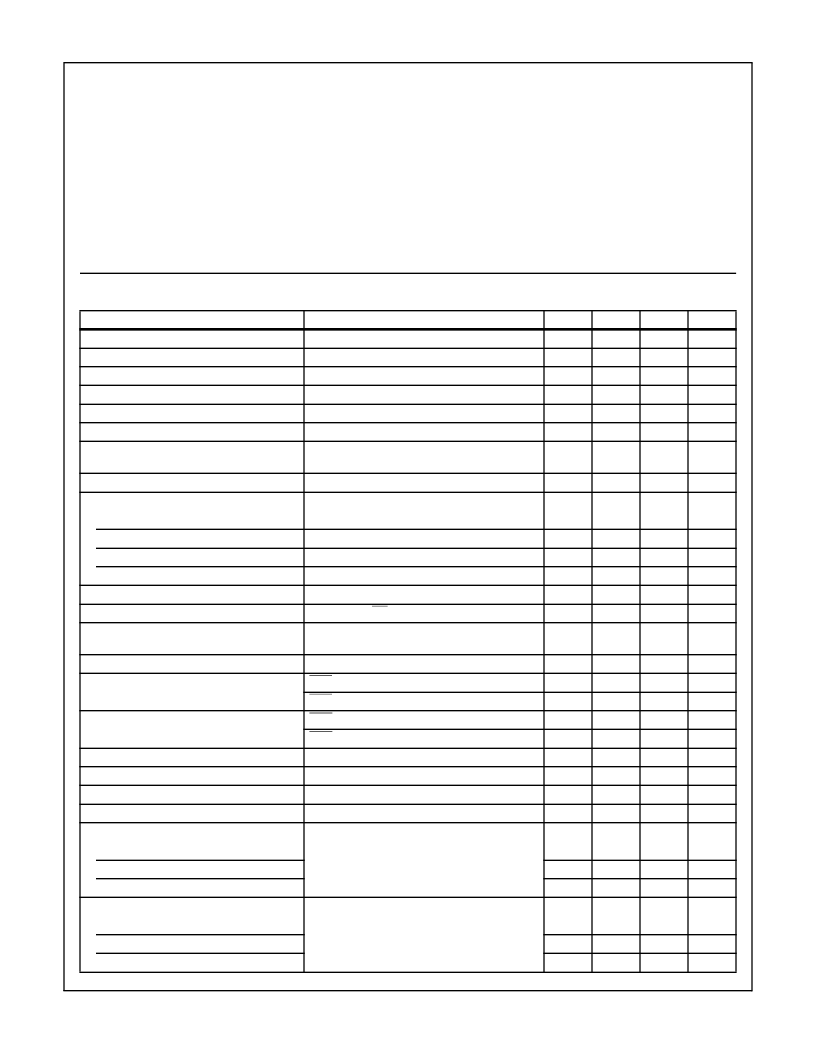
Specifications HC-5504DLC
Absolute Maximum Ratings
(Note 1)
Operating Conditions
Maximum Continuous Supply Voltages
(V
B
-) . . . . . . . . . . . . . . . . . . . . . . . . . . . . . . . . . . . . . -60 to +0.5 V
(V
B
+). . . . . . . . . . . . . . . . . . . . . . . . . . . . . . . . . . . . . -0.5 to +15 V
(V
B
+ - V
B
-) . . . . . . . . . . . . . . . . . . . . . . . . . . . . . . . . . . . . . . +75V
Relay Drive Voltage (V
RD
) . . . . . . . . . . . . . . . . . . . . . . .-0.5 to +15V
Junction Temperature Ceramic . . . . . . . . . . . . . . . . . . . . . . +175
o
C
Junction Temperature Plastic. . . . . . . . . . . . . . . . . . . . . . . . +150
o
C
Lead Temperature (Soldering 10 Sec.) . . . . . . . . . . . . . . . . +300
o
C
Operating Temperature Range
HC-5504DLC-5 . . . . . . . . . . . . . . . . . . . . . . . . . . . . 0
o
C to +75
o
C
HC-5504DLC-9 . . . . . . . . . . . . . . . . . . . . . . . . . . .-40
o
C to +85
o
C
Storage Temperature Range . . . . . . . . . . . . . . . . . . -65
o
C to 150
o
C
Relay Driver Voltage (V
RD
). . . . . . . . . . . . . . . . . . . . . . . +5 to +12V
Positive Supply Voltage (V
B
+). . . . . . . 4.75 to 5.25 or 10.8 to 13.2V
Negative Supply Voltage (V
B
-) . . . . . . . . . . . . . . . . . . . . -42 to -58V
High Level Logic Input Voltage . . . . . . . . . . . . . . . . . . . . . . . . . 2.4V
Low Level Logic Input Voltage . . . . . . . . . . . . . . . . . . . . . . . . . 0.6V
Loop Resistance (R
L
) . . . . . . . . . . . . . . . . . . . . . . . . . 200 to 1200
CAUTION: Stresses above those listed in “Absolute Maximum Ratings” may cause permanent damage to the device. This is a stress only rating and operation
of the device at these or any other conditions above those indicated in the operational sections of this specification is not implied.
Electrical Specifications
Unless Otherwise Specified, V
- = -48V, V
+ = +12V and +5V, AG = BG = DG = 0V, Typical Parameters
T
A
= +25
o
C. Min-Max Parameters are Over Operating Temperature Range.
PARAMETER
CONDITIONS
MIN
TYP
MAX
UNITS
On Hook Power Dissipation
I
LONG
* = 0, V
B
+ = +12V
R
L
= 600
, I
LONG
* = 0, V
B
+ = +12V
R
L
= 600
, I
LONG
* = 0, T
A
= -40
o
C
R
L
= 600
, I
LONG
* = 0, T
A
= +25
o
C
R
L
= 600
, I
LONG
* = 0
R
L
= 1200
, I
LONG
* = 0
R
L
= 1200
, V
B
- = -42V, I
LONG
* = 0
T
A
= +25
o
C
R
L
= 200
, I
LONG
* = 0
-
170
235
mW
Off Hook Power Dissipation
-
425
550
mW
Off Hook IB+
-
-
6.0
mA
Off Hook IB+
-
-
5.3
mA
Off Hook IB-
-
35
41
mA
Off Hook Loop Current
-
21
-
mA
Off Hook Loop Current
17.5
-
-
mA
Off Hook Loop Current
36
41
48
mA
Fault Currents
TIP to Ground
-
14
-
mA
RING to Ground
-
55
-
mA
TIP to RING
-
41
-
mA
TIP and RING to Ground
-
55
-
mA
Ring Relay Drive V
OL
Ring Relay Driver Off Leakage
I
OL
= 62mA
V
RD
= +12V, RC = 1 = HIGH, T
A
= +25
o
C
R
L
= 600
-
0.2
0.5
V
-
-
100
μ
A
Ring Trip Detection Period
-
2
3
Ring
Cycles
On Hook Ringing Current
-
-
30
mApk
Switch Hook Detection Threshold
SHD = V
OL
SHD = V
OH
GKD = V
OL
GKD = V
OH
R
L
= 200
18
-
-
mA
-
-
12
mA
Ground Key Detection Threshold
20
-
-
mA
-
-
10
mA
Loop Current During Power Denial
-
±
2
-
mA
Dial Pulse Distortion
0
-
5
ms
Receive Input Impedance
(Note 2)
-
110
-
k
Transmit Output Impedance
(Note 2)
-
10
20
Two Wire Return Loss
(Referenced to 600
+ 2.16
μ
F), (Note 2)
SR
L
LO
ER
L
SR
L
HI
Longitudinal Balance
-
15.5
-
dB
-
24
-
dB
-
31
-
dB
1V
RMS
200Hz - 3400Hz, (Note 2) IEEE Method
2 Wire Off Hook
58
65
-
dB
2 Wire On Hook
60
63
-
dB
4 Wire Off Hook
0
o
C
≤
T
A
≤
+75
o
C
50
58
-
dB
相關(guān)PDF資料 |
PDF描述 |
|---|---|
| HC1-5504B-9 | EIA/ITU PABX SLIC with 40mA Loop Feed |
| HC4P5504B1- | ITU Low Cost, PABX SLIC With 40mA Loop Feed |
| HC5503C | Unbalanced PBX/ Key System SLIC,Subscriber Line Interface Circuit(用戶線接口電路) |
| HC5503PRCBZ | Low Cost SLIC For Large Telecom Switches |
| HC5503PRCBZ96 | Low Cost SLIC For Large Telecom Switches |
相關(guān)代理商/技術(shù)參數(shù) |
參數(shù)描述 |
|---|---|
| HC1-5504B-7 | 制造商:未知廠家 制造商全稱:未知廠家 功能描述:Subscriber Line Interface Circuit |
| HC1-5504B-9 | 制造商:INTERSIL 制造商全稱:Intersil Corporation 功能描述:EIA/ITU PABX SLIC with 40mA Loop Feed |
| HC1-5504DLC-5 | 制造商:INTERSIL 制造商全稱:Intersil Corporation 功能描述:SLIC Subscriber Line Interface Circuit |
| HC1-5504DLC-9 | 制造商:INTERSIL 制造商全稱:Intersil Corporation 功能描述:SLIC Subscriber Line Interface Circuit |
| HC1-5504X | 制造商:Harris Corporation 功能描述: |
發(fā)布緊急采購(gòu),3分鐘左右您將得到回復(fù)。