- 您現(xiàn)在的位置:買賣IC網(wǎng) > PDF目錄379167 > DM5495 PDF資料下載
參數(shù)資料
| 型號: | DM5495 |
| 文件頁數(shù): | 4/10頁 |
| 文件大小: | 133K |
| 代理商: | DM5495 |
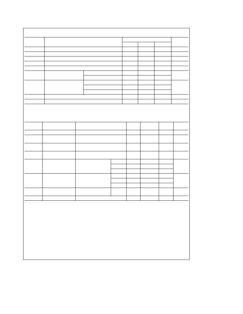
Recommended Operating Conditions
Symbol
Parameter
DM7493A
Units
Min
Nom
Max
V
CC
Supply Voltage
4.75
5
5.25
V
V
IH
2
V
V
IL
Low Level Input Voltage
0.8
V
I
OH
High Level Output Current
b
0.8
mA
I
OL
Low Level Output Current
16
mA
f
CLK
Clock Frequency
(Note 5)
A
0
32
MHz
B
0
16
t
W
Pulse Width
(Note 5)
A
15
B
30
ns
Reset
15
t
REL
Reset Release Time (Note 5)
25
ns
§
C
T
A
Free Air Operating Temperature
0
70
’93A Electrical Characteristics
over recommended operating free air temperature range (unless otherwise noted)
Symbol
Parameter
Conditions
Min
Typ
Max
Units
(Note 1)
V
I
Input Clamp Voltage
V
CC
e
Min, I
I
e b
12 mA
V
CC
e
Min, I
OH
e
Max
V
IL
e
Max, V
IH
e
Min
V
CC
e
Min, I
OL
e
Max
V
IH
e
Min, V
IL
e
Max (Note 4)
V
CC
e
Max, V
I
e
5.5V
b
1.5
V
V
OH
High Level Output
Voltage
2.4
3.4
V
V
OL
Low Level Output
Voltage
0.2
0.4
V
I
I
Input Current
@
Max
Input Voltage
1
mA
I
IH
High Level Input
Current
V
CC
e
Max
V
I
e
2.4V
Reset
40
A
80
m
A
B
80
I
IL
Low Level Input
Current
V
CC
e
Max
V
I
e
0.4V
Reset
b
1.6
A
b
3.2
mA
B
b
3.2
I
OS
Short Circuit
Output Current
V
CC
e
Max
(Note 2)
b
18
b
57
mA
I
CC
Note 1:
All typicals are at V
CC
e
5V, T
A
e
25
§
C.
Note 2:
Not more than one output should be shorted at a time.
Supply Current
V
CC
e
Max (Note 3)
26
39
mA
Note 3:
I
CC
is measured with all outputs open, both R0 inputs grounded following momentary connection to 4.5V and all other inputs grounded.
Note 4:
Q
A
outputs are tested at I
OL
e
Max plus the limit value of I
IL
for the B input. This permits driving the B input while maintaining full fan-out capability.
Note 5:
T
A
e
25
§
C and V
CC
e
5V.
4
相關PDF資料 |
PDF描述 |
|---|---|
| DM5492AJ | Asynchronous Up Counter |
| DM7492AN | Asynchronous Up Counter |
| DM71LS98J | Three-State Octal Buffers |
| DM71LS95J | Three-State Octal Buffers |
| DM71LS96 | Three-State Octal Buffers |
相關代理商/技術參數(shù) |
參數(shù)描述 |
|---|---|
| DM5495 WAF | 制造商:Texas Instruments 功能描述: |
| DM5495J | 制造商:Rochester Electronics LLC 功能描述: |
| DM5496 | 制造商:未知廠家 制造商全稱:未知廠家 功能描述:5-Bit Shift Registers |
| DM5496 WAF | 制造商:Texas Instruments 功能描述: |
| DM5497 WAF | 制造商:Texas Instruments 功能描述: |
發(fā)布緊急采購,3分鐘左右您將得到回復。