- 您現(xiàn)在的位置:買賣IC網(wǎng) > PDF目錄373963 > AD9501SQ (ANALOG DEVICES INC) Digitally Programmable Delay Generator PDF資料下載
參數(shù)資料
| 型號: | AD9501SQ |
| 廠商: | ANALOG DEVICES INC |
| 元件分類: | 模擬信號調(diào)理 |
| 英文描述: | Digitally Programmable Delay Generator |
| 中文描述: | SPECIALTY ANALOG CIRCUIT, CDIP20 |
| 封裝: | CERDIP-20 |
| 文件頁數(shù): | 9/12頁 |
| 文件大小: | 180K |
| 代理商: | AD9501SQ |
AD9501
REV. A
–9–
T his delay matching is often difficult when using high speed,
high-pin-count testers because lead length and circuit
impedance can change when the tester setup is changed for
different types of devices. T he skew which might result from
these changes can be compensated by using AD9501 units as
shown in Figure 5.
When deskewing multiple signal paths, a single stimulus pulse is
applied to all inputs of the AD9501s which are used. T he delay
for each signal path is then measured by the tester’s delay
measurement circuit. Using a closed loop technique, all delays
are equalized by changing the digital value held in the register of
each AD9501. Once all delays have been matched to the desired
tolerance, the calibration loop is opened; and the tester is ready
to test the new type of device.
Digitally Programmable Oscillator
T wo AD9501s can be configured as an stable oscillator, as
shown in Figure 6.
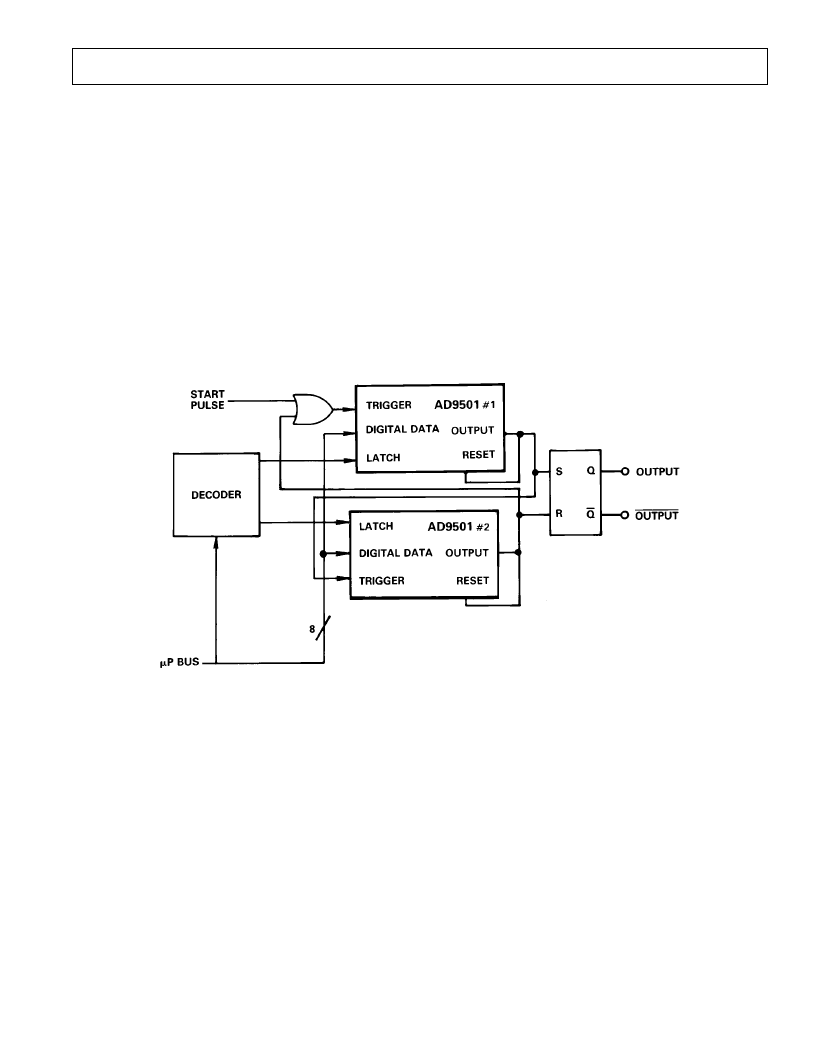
triggered from a common clock signal. T heir outputs go to the
inputs of an RS flip-flop. A digital delay value is applied as an
input to each with AD9501 #2 typically having a larger value
than AD9501 #1.
As shown by the timing portion of the diagram, changing the
delay value from one clock cycle to the next generates a pseudo-
random pulse whose leading and trailing edge delays are con-
trolled relative to Clock In. T he dashed lines illustrate how the
programmed delays of the AD9501 components control both
the timing and width of the generator output.
T he frequency (f) and pulse width (t
pw
) of the pulse generator
can be determined as follows:
f
=
f
CLOCK IN
and:
t
pw
=
t
TOT
2
±
t
TOT
1
Figure 6. Digitally Programmable Oscillator
Delay through each side of the oscillator is determined by the
programmed delay (t
D
) of each AD9501 plus the minimum
propagation delay (t
PD
) of each. Increasing the digital value
applied to either AD9501 decreases frequency, just as
increasing RC decreases frequency in an analog ring oscillator.
Using a pair of AD9501 Delay Generators as shown allows the
user great flexibility because both the frequency and the duty
cycle of the oscillator are easily controlled.
Frequency of the oscillator output can be established with the
equation:
f
=
1/(2
t
PD
+
t
D
1
+
t
D
2
)
when t
D1
and t
D2
are the programmed delays of AD9501 #1 and
AD9502 #2, respectively.
Programmable Pulse Generator
In this application, shown in Figure 7, two AD9501 units are
with T
T OT
being equal to each AD9501’s minimum propagation
delay (t
PD
) plus programmed delay (t
D
). If both AD9501s are
set for the same full-scale delay range, their minimum
propagation delays will be approximately the same, and the
pulse width will be approximately equal to the difference in
programmed delays.
Digital Delay Detector
An unknown digital delay can be measured by applying a
repetitive clock to the circuit shown in Figure 8.
T he pictured delay detector works in a manner similar to a
successive approximation ADC; in this circuit, however, a
D-type flip-flop replaces the ADC’s voltage comparator.
T o calibrate the circuit, short out the unknown delay and apply
the clock input to both AD9501 units.
相關(guān)PDF資料 |
PDF描述 |
|---|---|
| AD9501JQ | Digitally Programmable Delay Generator |
| AD9502 | Hybrid RS-170 Video Digitizer |
| AD9502AM | Hybrid RS-170 Video Digitizer |
| AD9502BM | Hybrid RS-170 Video Digitizer |
| AD9502CM | Hybrid RS-170 Video Digitizer |
相關(guān)代理商/技術(shù)參數(shù) |
參數(shù)描述 |
|---|---|
| AD9502 | 制造商:AD 制造商全稱:Analog Devices 功能描述:Hybrid RS-170 Video Digitizer |
| AD9502(RS-170) | 制造商:AD 制造商全稱:Analog Devices 功能描述:Hybrid RS-170 Video Digitizer |
| AD9502AM | 制造商:AD 制造商全稱:Analog Devices 功能描述:Hybrid RS-170 Video Digitizer |
| AD9502AMB | 制造商:未知廠家 制造商全稱:未知廠家 功能描述:Video Generator & Line Lock Circuit |
| AD9502BM | 制造商:AD 制造商全稱:Analog Devices 功能描述:Hybrid RS-170 Video Digitizer |
發(fā)布緊急采購,3分鐘左右您將得到回復(fù)。